
How to use the end plate connection calculator
A bolted moment connection by the component method: what each input means, how to read the joint resistance, and which component governs.
1. What the calculator does
The bolted end plate calculator checks a moment connection between a steel beam and a column: an end plate welded to the beam and bolted to the column flange, flush or extended above the beam. It uses the component method: it finds the tension resistance of each bolt row from the end plate, the bolts and the column flange and web, the compression at the bottom flange, the web panel shear and the bolt shear, and builds the moment and shear resistance of the joint from them.
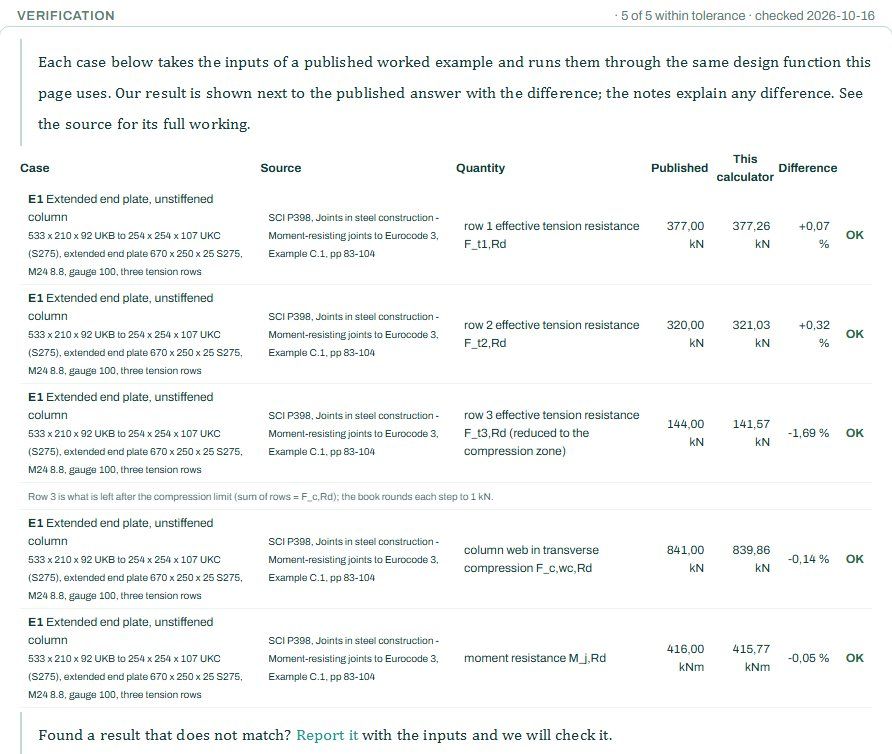
The code route is the EN 1993-1-8 component method (clause 6.2), with the South African (SAISC / SANS) section tables. The badge says it runs the STATIX connection engine, with published-example checks.

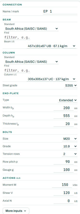
2. The inputs, group by group
| Input | What it means | Typical value |
|---|---|---|
| Beam and column | The beam and column sections from the tables, and the steel grade. | 457×191×67 UB to 305×305×137 UC, S355 |
| End plate | Extended or flush, width, depth and thickness. | extended, 200 × 555 × 20 |
| Bolts | Size, grade, number of tension rows, row pitch and gauge. | M20 10.9, 2 tension rows, pitch 90, gauge 100 |
| Actions (ULS) | Factored moment, shear and axial force at the joint. | M 150 kNm, V 120 kN, N 0 |
| More inputs | The frame type for the stiffness classification and other options. | defaults |
3. How to read the result
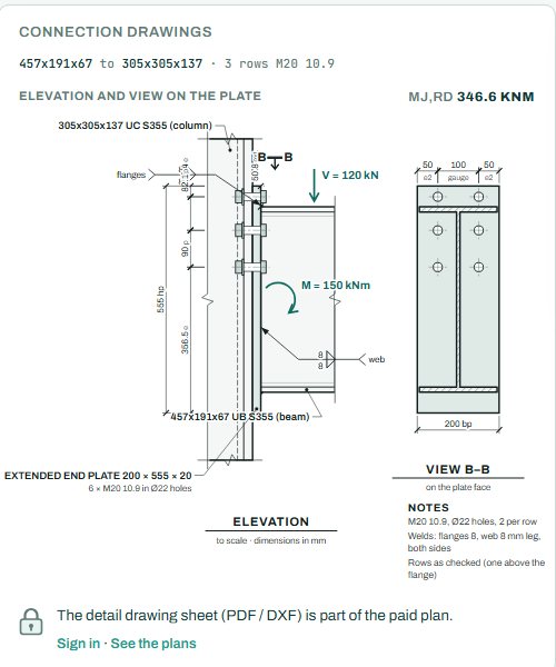
The drawings show the elevation and the view on the plate to scale, with the bolt rows, the welds and the moment resistance Mj,Rd in the header.
The joint resistance card lists the moment resistance, the shear resistance, the compression resistance, the web panel shear, the top-row tension, the critical row with its lever arm, the governing component and the utilisation. Compare M with Mj,Rd and V with Vj,Rd; the worse of the two (and the other components) sets the utilisation.
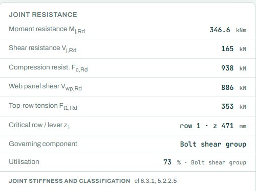
The badge names the governing component; here the bolt shear group (120 kN against 165 kN), not the moment (150 against 346.6 kNm). More shear bolts below the tension rows, or bigger bolts, fix that. The stiffness and classification line says whether the joint is rigid, semi-rigid or pinned for the frame analysis. Anything the engine could not run shows as NOT CHECKED.
4. Calc sheet and take-off
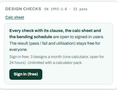
The result (pass / fail and utilisation) stays free for everyone. Every check with its clause, the calc sheet and the bending schedule are open to signed-in users. Sign in free: 3 designs a month (one calculator, open for 24 hours). Unlimited with a calculator pack.
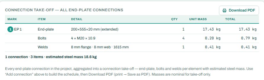
The detail drawing sheet (PDF / DXF) is part of the paid plan. The connection take-off collects every connection of this type in the project, with the plate, bolts, welds and steel mass.
5. A 2-minute walk-through
- Open the calculator: a 457×191×67 UB to a 305×305×137 UC with an extended 20 mm end plate and M20 10.9 bolts, M 150 kNm and V 120 kN.
- Read the badge: PASS 73 %, bolt shear group.
- Raise M to 300 kNm and see which component governs next.
- Change the plate to flush and see Mj,Rd drop.
- Thin the plate to 15 mm and watch the tension rows change mode.
6. Common mistakes
- Only the moment. The shear on the bolts below the tension rows often governs, as here.
- A thick plate “to be safe”. A thick plate can move the failure to the bolts, which is brittle; the plate yielding first is the ductile mode.
- Ignoring the column. The column flange and web in tension, compression and shear are components too; a light column may need stiffeners; read the column components in the joint resistance card.
- A rigid frame with a semi-rigid joint. Check the classification against what the frame analysis assumed.
8. Learn more
- Steel Design 1, lesson 5: bolted connections and Steel Design 2, lesson 5: the eaves haunch
- Worked example: end plate connection to EN 1993-1-8
- Guide: the eaves haunch calculator
Open the end plate connection calculator
A guide to using the calculator, not a design. Check every value against the current code and your own project, and have the design checked and signed by a registered professional engineer.
Be first to use STATIX 3D and STATIX 2D.
Leave your email and we will tell you when each part is ready for testing. One confirmation now, one message then. A short monthly update only if you tick the box.