
Steel beam-column design to SANS 10162-1
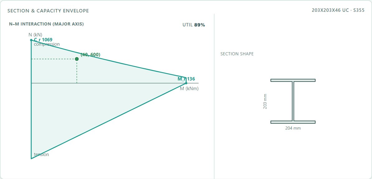
A 203 × 203 × 46 H-section in S355, 4 m long, carrying 600 kN and 40 kNm: section class, column buckling, lateral-torsional buckling with Mcr, shear and the cl. 13.8 interaction. Every number below comes from the free STATIX steel member calculator and was checked by hand.
1. The problem
| Input | Value |
|---|---|
| Section | 203 × 203 × 46 H-section (universal column), hot-rolled |
| Steel | S355: fy = 355 MPa, E = 200,000 MPa, G = 77,000 MPa |
| Length | 4.0 m, pinned both ends, K = 1.0 about both axes, braced frame |
| Design loads (ultimate, already factored) | Cu = 600 kN, Mux = 40 kNm (major axis), Muy = 0, Vu = 120 kN |
| Lateral restraint | none between the ends: unbraced length for LTB = 4.0 m |
| Moment gradient | ω2 = 1.0 (uniform moment, the safe value); ω1 = 1.0 |
All resistance factors are φ = 0.9. Axes follow SANS 10162-1: x-x is the major axis, y-y the minor axis.
2. Section properties
| Property | Calculator library | SAISC Red Book |
|---|---|---|
| A | 5,870 mm² | 5,880 mm² |
| h × b × tw × tf | 203.2 × 203.6 × 7.2 × 11.0 mm | 203.2 × 203.2 × 7.3 × 11.0 mm |
| Ix / Iy | 45.68 / 15.48 × 10⁶ mm⁴ | 45.6 / 15.4 × 10⁶ mm⁴ |
| Ze,x / Zpl,x | 450 / 497 × 10³ mm³ | 449 / 497 × 10³ mm³ |
| Ze,y / Zpl,y | 152 / 231 × 10³ mm³ | 151 / 230 × 10³ mm³ |
| rx / ry | 88.2 / 51.4 mm | 88.1 / 51.2 mm |
| J | 203 × 10³ mm⁴ | 225 × 10³ mm⁴ |
| Cw | Iy(h − tf)²/4 = 143 × 10⁹ mm⁶ | 142 × 10⁹ mm⁶ |
The two sets agree to within 1%, except the torsion constant J, which the library has about 10% below the Red Book. A lower J gives a lower Mcr, so the library value is on the safe side. With the Red Book values every result below changes by less than 1%.
3. Section class (SANS 10162-1 cl. 11, Table 4)
For the flange of an I-section the width b is half the full flange width (cl. 11.3.1c). The web width is the clear distance between the flanges (cl. 11.3.2c).
Class 3 means the section reaches first yield but not the full plastic moment. Bending resistance is based on the elastic modulus Ze, not Zpl. Many H-sections in S355 are class 3 for this reason, while the same section in 300WA would be class 2.
4. Axial compression (cl. 13.3.1)
n = 2.24 applies only to welded three-plate members with flame-cut flange edges and to hot-formed or stress-relieved hollow sections. A rolled H-section always takes n = 1.34. The calculator uses 1.34 for every section, which is safe for the others.
5. Lateral-torsional buckling (cl. 13.6)
The compression flange is free over the full 4 m, so the moment resistance is limited by lateral-torsional buckling. For a class 3 section cl. 13.6(b) uses the yield moment My.
ω2 = 1.0 is the value for uniform moment, the worst case. If the moment varies linearly between the ends, cl. 13.6(a) gives ω2 = 1.75 + 1.05κ + 0.3κ² ≤ 2.5. Here κ is the ratio of the smaller to the larger end moment, positive for double curvature and negative for single curvature. Uniform moment is κ = −1 and gives ω2 = 1.0. A beam with one end moment zero is κ = 0 and gives 1.75. Getting the sign wrong turns 1.0 into 2.5.
6. Minor-axis bending (cl. 13.5)
There is no minor-axis moment in this example, but the resistance is still reported. For a class 3 section cl. 13.5(b) uses the elastic modulus about both axes.
7. Shear (cl. 13.4.1.1)
kv = 5.34 is the value for a web without transverse stiffeners.
8. Axial load and bending (cl. 13.8.3)
The section is class 3, so cl. 13.8.3 applies (all sections except class 1 and class 2 I-shapes). Its coefficients are 1.0 on both moment terms. Class 1 and 2 I-shapes use cl. 13.8.2 with 0.85 and β.
Case (c) governs, as it usually does for an unrestrained column in bending: the weak-axis buckling load and the LTB moment are both the lowest values of their kind. U1x = 1.119 means the 40 kNm grows by about 12% from the member's own deflection under 600 kN.
In case (b) the calculator uses the weak-axis Cr. For bending about the strong axis only, cl. 13.8.2(b) lets you use Cr = Crx = 1,575 kN, which gives 0.381 + 0.311 = 0.69. The calculator's 0.87 is on the safe side, and case (c) governs either way.
9. Result
| Check | Result |
|---|---|
| Section class | Class 3 (flange b/t = 9.25 > 9.02) |
| Axial compression | 600 ≤ 1,069 kN (56%) |
| Major-axis bending with LTB | 40 ≤ 136.0 kNm (29%), Mcr = 252 kNm |
| Minor-axis bending resistance | 48.6 kNm (no demand) |
| Shear | 120 ≤ 308.5 kN (39%) |
| Interaction, cl. 13.8.3(c) | 0.89 ≤ 1.0 |
| Mass | 46.1 kg/m × 4.0 m = 184 kg |
The member works at 89%. The two cheap ways to more capacity are a lateral restraint at mid-height (halves the LTB and weak-axis lengths) and a real ω2 if the moment is not uniform.
Open the free steel member calculator
A worked example for learning, not a design. Check every value against the current code and your own project, and have the design checked and signed by a registered professional engineer.
Be first to use STATIX 3D and STATIX 2D.
Leave your email and we will tell you when each part is ready for testing. One confirmation now, one message then. A short monthly update only if you tick the box.