
Cantilever retaining wall to SANS 10100
A 3 m cantilever retaining wall with a 10 kPa surcharge: earth pressure, overturning, sliding, bearing, and the steel and shear in the stem, toe and heel. Every number below comes from the free STATIX retaining wall calculator and was checked by hand.
1. The problem
| Input | Value |
|---|---|
| Retained height (top of backfill to underside of base) | H = 3.0 m |
| Stem | 350 mm thick, vertical, 2.6 m high above the base |
| Base | 400 mm thick: toe 0.7 m + stem 0.35 m + heel 2.0 m = B = 3.05 m |
| Backfill | level, φ = 30°, γ = 18 kN/m³, no cohesion, no wall friction, no water |
| Surcharge on the backfill | q = 10 kPa |
| Soil in front of the toe | 0.6 m deep, φ = 30°, γ = 18 kN/m³ |
| Base friction and bearing | μ = 0.5, qall = 150 kPa |
| Materials | fcu = 30 MPa, fy = 450 MPa, concrete 25 kN/m³, cover 50 mm (stem) and 60 mm (base) |
| Targets | overturning 2.0, sliding 1.5 |
Everything is per metre run of wall.
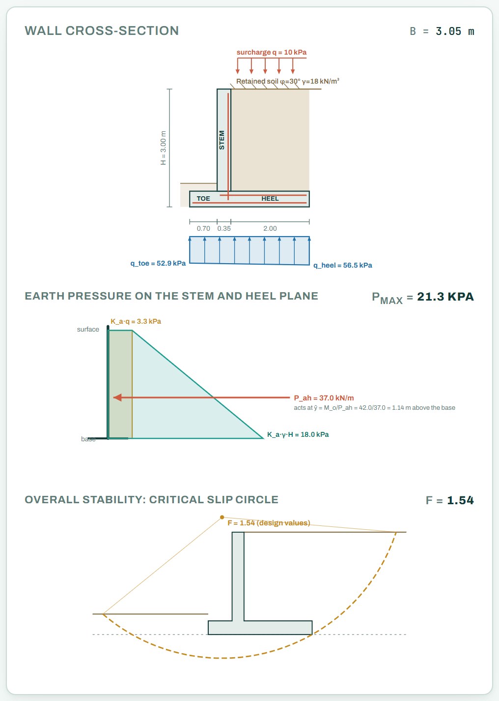
2. Earth pressure (Rankine)
With a level backfill and no wall friction, Rankine gives the active pressure. The thrust acts on a vertical plane through the back of the heel, over the full height H.
The pressure at the base is KaγH + Kaq = 18.0 + 3.3 = 21.3 kPa.
3. Weights and restoring moment
Lever arms are measured from the front edge of the toe.
| Item | Weight (kN/m) | Arm (m) | Moment (kNm/m) |
|---|---|---|---|
| Stem 0.35 × 2.6 × 25 | 22.75 | 0.875 | 19.9 |
| Base 3.05 × 0.4 × 25 | 30.50 | 1.525 | 46.5 |
| Soil on heel 2.0 × 2.6 × 18 | 93.60 | 2.050 | 191.9 |
| Surcharge on heel 2.0 × 10 | 20.00 | 2.050 | 41.0 |
| Total with surcharge | 166.85 | 299.3 | |
| Total without surcharge | 146.85 | 258.3 |
The surcharge pushes the wall over, but the part of it standing on the heel also holds the wall down. You cannot count on it for both. SANS 10160-1 puts a factor of 0 on a variable action where it helps, so the stability checks leave it off the heel and keep it on the driving side.
4. Overturning
5. Sliding
Friction under the base and passive resistance of the soil in front of the toe hold the wall back.
This example counts full passive pressure over the 0.6 m in front of the toe (the calculator lets you switch it off). That soil can be dug out for services or washed away, and passive pressure needs movement to develop. Many engineers ignore it, or the top 0.5 m of it. Without it here: 73.4 / 37.0 = 1.98, still above 1.5. The friction factor μ = 0.5 is an input; tan(⅔φ) = 0.36 is a common cautious value for concrete cast on this soil.
6. Bearing pressure
Bearing is the one check where the surcharge on the heel is unfavourable: it adds load. So check it with the surcharge on as well as off, and take the worse.
Without the surcharge on the heel the pressure runs from 53.1 kPa at the toe to 43.2 kPa at the heel. That case is used for the heel design below, because it gives the least upward help to the heel.
7. Stem (SANS 10100 cl. 4.3.3 and 4.3.4)
The stem is a vertical cantilever loaded over its own height of 2.6 m. The calculator uses the SANS 10160-1 STR factors: 1.2 on the soil pressure (permanent) and 1.6 on the surcharge pressure (variable).
For vc the calculator takes As as the steel required (455 mm²/m), not the 503 mm²/m provided. That gives a slightly lower vc, on the safe side. It does the same for the toe and the heel below.
Under SANS 10160-1 earth pressure is a permanent action (factor 1.2) and the surcharge a variable one (factor 1.6). The single 1.5 is on the safe side unless the surcharge is larger than about γH, which only happens on short walls under heavy traffic.
8. Toe (bottom steel)
The toe is a cantilever pushed up by the ground, so its tension face is the bottom. For bending the calculator takes the highest pressure at the toe edge, 53.1 kPa, from the surcharge-free case. For shear it takes the case that puts the most upward load on the toe, which here is the one with the surcharge on: 52.9 kPa at the edge and 53.7 kPa at the stem face.
Minimum steel governs the toe by a wide margin.
9. Heel (top steel)
The heel carries the soil, surcharge and its own weight down, and the ground pushes it up. The load down wins, so the heel bends with tension on top. The calculator factors the load down (1.2 on the soil and slab, 1.6 on the surcharge) and takes off the bearing pressure up under the same load case.
9b. Stability to SANS 10160 (design values)
Besides the global factors of safety above, the calculator checks the wall with the SANS 10160 partial factors on the soil and the actions (GEO and EQU), the bearing resistance of the ground to EN 1997-1 Annex D, and a slip circle through the soil behind and under the wall:
10. Result
| Check | Result |
|---|---|
| Overturning | FoS 6.15 ≥ 2.0 |
| Sliding | FoS 2.25 ≥ 1.5 (1.98 without passive) |
| Bearing | 56.5 kPa ≤ 150 kPa, whole base in contact |
| Stem | Y12 at 225 (soil face), minimum steel governs; shear 0.130 ≤ 0.330 MPa |
| Toe | Y12 at 200 (bottom face), minimum steel governs; shear 0.116 ≤ 0.320 MPa |
| Heel | Y16 at 300 (top face); shear 0.242 ≤ 0.350 MPa |
| Sliding, GEO (SANS 10160-5) | 49.1 ≤ 66.7 kN/m, the most highly used check at 74% |
Sliding is the check to watch. A shear key under the base, or a longer heel, are the usual fixes when sliding fails.
Open the free retaining wall calculator
A worked example for learning, not a design. Check every value against the current code and your own project, and have the design checked and signed by a registered professional engineer.
Be first to use STATIX 3D and STATIX 2D.
Leave your email and we will tell you when each part is ready for testing. One confirmation now, one message then. A short monthly update only if you tick the box.