
RC column design to SANS 10100
A short braced 400 mm square column under axial load and bending: slenderness, minimum eccentricity, axial capacity, the N–M interaction by strain compatibility, steel limits and links. Every number below comes from the free STATIX RC column calculator and was checked by hand.
1. The problem
| Input | Value |
|---|---|
| Section | 400 × 400 mm rectangular column, cover 40 mm |
| Design loads (ultimate, already factored) | N = 1,500 kN, Mx = 80 kNm, My = 0, V = 0 |
| Effective length | le = 3.0 m about both axes, braced |
| Materials | fcu = 30 MPa, fy = 450 MPa |
The calculator asks for the effective length, not the clear height. You find it as le = β × lo, with β from Table 18 of SANS 10100 for a braced column (0.75 to 1.0, depending on how stiff the beams at each end are). Here le = 3.0 m is given.
2. Slenderness (SANS 10100 cl. 4.7.1.4)
Check both directions. A column can be short about one axis and slender about the other. This one is square, so the two ratios are the same.
The braced limit depends on the ratio of the smaller to the larger end moment. With the end moments unknown, the calculator takes M1/M2 = 1, which gives the lowest limit, 10. With real end moments in double curvature the limit is higher. At 7.5 this column is short either way.
3. Minimum eccentricity (cl. 4.7.2.3)
No column is designed for pure axial load. The design moment must be at least N × emin, about each axis separately.
4. Steel: minimum governs
The calculator starts at the minimum steel and adds more only if the column fails. Here the minimum is already enough. It lays the six bars out symmetrically: one at each corner and one in the middle of each face at right angles to the bending, so 3 bars (339 mm²) on the top face and 3 on the bottom face.
The calculator measures the bar depth as cover + 10 mm link + 8 mm (half a 16 mm bar) = 58 mm, even for 12 mm bars. The true depth is 56 mm, so it slightly under-rates the section. That is on the safe side.
5. Axial capacity Nuz (cl. 4.7.3.1)
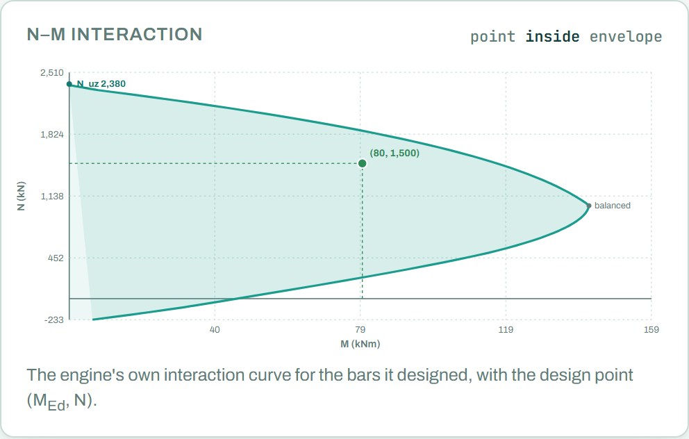
SANS 10100 gives Nuz with 0.75fy on the steel; the allowance for the material factor is built in. This is the axial capacity with no moment at all and is the top of the interaction diagram. The real check is the interaction in the next step.
6. N–M interaction by strain compatibility (cl. 4.7.4.1)
SANS 10100 designs a column section with the same assumptions as a beam (cl. 4.3.3.1). Pick a neutral axis depth x. The concrete strain at the compressed face is 0.0035. The steel in compression works up to fyc = fy / (1.15 + fy/2000) = 450 / 1.375 = 327 MPa (SANS 10100-1 figure 2), not 0.87 fy. The stress block is 0.45 fcu (0.447 fcu exactly, 0.67/1.5) over a depth 0.9x. The steel stress follows its strain, up to 0.87 fy = 391.5 MPa. Move x until the internal forces add up to N = 1,500 kN. The moment of those forces about the centre is the moment capacity.
At 1,500 kN the neutral axis sits deep in the section and the bottom steel is barely in tension. That is normal for a column carrying a lot of axial load. The biggest moment this section can carry is about 142 kNm, at an axial load near 1,035 kN.
For bending about y the two middle bars sit on the centre line, where they carry axial load but add no moment, so the capacity about y is lower than about x. Bending can reverse in a real frame; the bars are the same on opposite faces, so the capacity is the same either way round.
7. Links (cl. 4.11.4.5.1)
The 12φ rule stops the compression bars from buckling between links. The code also asks that every corner bar and every alternate bar is held by a link corner of 135° or less, and that every other bar is within 150 mm of a held bar. One perimeter link holds the 4 corner bars. The bar in the middle of each face is not held, but both its neighbours are, and it is 142 mm centre to centre from them: 130 mm clear, inside 150 mm. So one perimeter link is enough.
8. Shear (cl. 4.7.4.5)
If there were shear, it would be checked as for a beam, with vc from eq. (2) raised for the axial load by 0.6NVh/(AcM) (cl. 4.3.4.4, eq. 2(a)), with Vh/M not more than 1.
9. Result
| Check | Result |
|---|---|
| Slenderness | le/h = 7.5 ≤ 10: short |
| Axial capacity | 1,500 ≤ Nuz = 2,380 kN |
| N–M interaction about x | 80 ≤ 116.7 kNm at 1,500 kN (69%) |
| Minimum eccentricity about y | 30 ≤ 111.5 kNm (27%) |
| Longitudinal steel | 6Y12 = 679 mm² = 0.42% (0.4% to 6%) |
| Links | Y10 at 125 mm, one perimeter link |
| Quantities (3 m length) | 6Y12 × 3.0 m and 25 links of 1,440 mm: about 38 kg of steel |
The bar lengths in the schedule are the effective length only. Add laps or starter bars for the real storey height.
Open the free RC column calculator
A worked example for learning, not a design. Check every value against the current code and your own project, and have the design checked and signed by a registered professional engineer.
Be first to use STATIX 3D and STATIX 2D.
Leave your email and we will tell you when each part is ready for testing. One confirmation now, one message then. A short monthly update only if you tick the box.