
RC beam design to SANS 10100
A simply supported reinforced concrete beam from load to bars: bending, shear links, minimum steel, bar fit, span/depth, crack width and long-term deflection. The numbers come from the free STATIX RC beam calculator; the ultimate-limit-state steps were checked by hand.
1. The problem
| Input | Value |
|---|---|
| Span | 6.0 m, simply supported |
| Design load (ultimate, already factored) | w = 20 kN/m over the full span |
| Section | 300 mm wide × 550 mm deep |
| Materials | fcu = 30 MPa, fy = 450 MPa |
| Cover to links | 40 mm, links 10 mm |
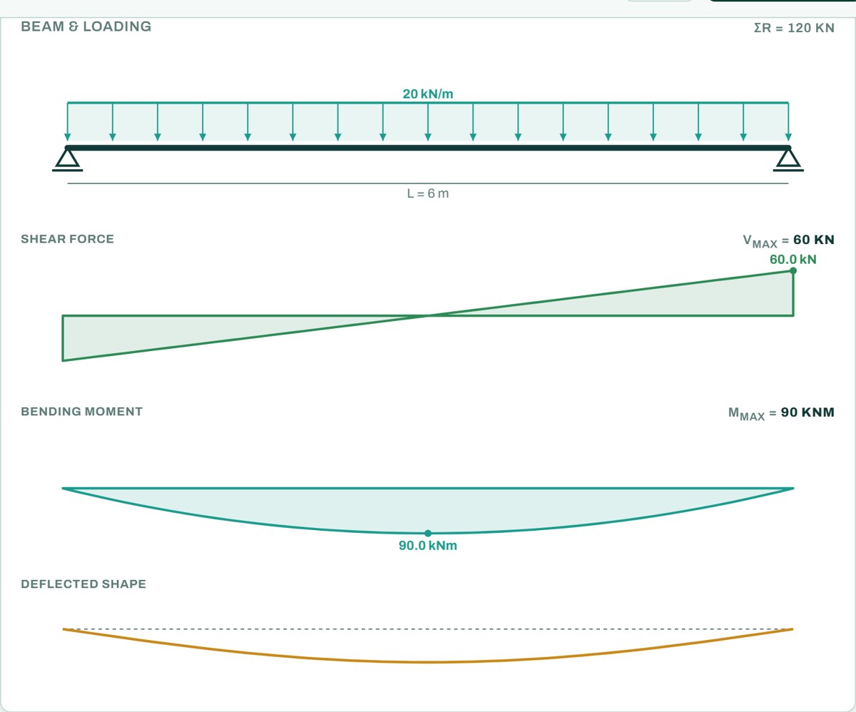
2. Design forces
3. Bending (SANS 10100 cl. 4.3.3)
With 12 mm bars the real effective depth is 494 mm, a little more than the 490 mm assumed, so the check is on the safe side. The calculator's design result uses d = 494 mm: K = 0.041 and As,req = 490 mm². The 5Y12 then give a moment resistance of 103.3 kNm, so the beam works at 87% in bending (90 / 103.3).
4. Shear (SANS 10100 cl. 4.3.4)
The calculator spaces the links a little wider. With d = 494 mm the limit is 0.75d = 370 mm, and it provides Y10 @ 350 mm, 18 links over the span. It also adds 2Y12 top bars as hangers, so each link has a bar to pass round in its top corners (cl. 4.11.6.4). Both spacings meet the nominal link rules; 300 mm is simply a rounder figure for site.
5. Detailing
6. Serviceability
In the calculator this load is entered as a dead load Gk = 16.67 kN/m with no live load (1.2 × 16.67 = 20 kN/m), so for the service stress it takes the service load as Gk = 16.67 kN/m, the ultimate load divided by 1.2, which is on the safe side. If the ends of the beam are nominally restrained, Table 10 allows a basic ratio of 20 instead of 16 (the calculator has a setting for this). The beam passes either way.
The calculator also checks crack control by the bar spacing rules and works out the long-term deflection with the BS 8110-2 method, using the service load Gk = 16.67 kN/m (service moment 75.0 kNm), creep factor 2.0 and shrinkage strain 300 × 10−6:
| Check | Result |
|---|---|
| Crack control: bar spacing | passes (86 % of the allowed spacing) |
| Long-term deflection | 20.3 mm ≤ L/250 = 24 mm |
Taking all of the load as service load is on the safe side. For a real design, work out the quasi-permanent load (permanent load plus ψ2 times imposed load) and use that.
7. Result
| Item | Result |
|---|---|
| Bottom steel | 5Y12 (565 mm²), one layer; 87% in bending |
| Top steel | 2Y12 hangers for the links |
| Links | Y10 @ 300 mm by hand, Y10 @ 350 mm in the calculator (both nominal, ≤ 0.75d) |
| Span/depth | 12.1 ≤ 22.0 |
| Reactions | 60 kN at each support; total 120 kN = applied load |
Open the free RC beam calculator
A worked example for learning, not a design. Check every value against the current code and your own project, and have the design checked and signed by a registered professional engineer.
Be first to use STATIX 3D and STATIX 2D.
Leave your email and we will tell you when each part is ready for testing. One confirmation now, one message then. A short monthly update only if you tick the box.