
Pad footing design to SANS 10100
A complete worked example: an isolated pad footing under a 400 mm square column, from self-weight and bearing pressure to bending, shear, punching and minimum steel, with the SANS 10160-1 load combinations. Every number below comes from the free STATIX pad footing calculator and was checked by hand.
1. The problem
| Input | Value |
|---|---|
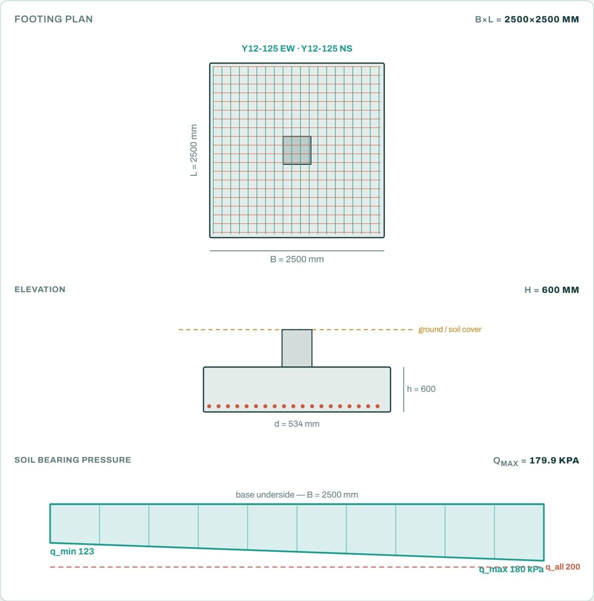
| Column | 400 × 400 mm, stub 0.5 m high |
| Characteristic loads at the top of the stub | permanent G: N = 550 kN, My = 20 kNm, Hx = 25 kN imposed Q: N = 250 kN, My = 10 kNm, Hx = 15 kN |
| Footing | 2.5 × 2.5 m on plan, 600 mm thick, 0.5 m of soil on top |
| Allowable bearing pressure | qall = 200 kPa |
| Materials | fcu = 30 MPa, fy = 450 MPa, cover 50 mm |
| Unit weights | concrete 24 kN/m³, soil 18 kN/m³ |
| Load combinations | SANS 10160-1: serviceability G + Q; ultimate STR 1.2G + 1.6Q and STR-P 1.35G + 1.0Q (the worse governs) |
2. Self-weight
The soil on top of the footing presses on the ground too, so it goes into the bearing check.
3. Bearing pressure (serviceability, G + Q)
The horizontal force acts at the top of the stub, 1.1 m above the underside of the footing, so it adds to the moment.
Overturning (safety factor 16) and sliding (safety factor 11.8 with μ = 0.5) are far from critical here.
4. Design pressure for bending and shear (ultimate)
Bending and shear use the net pressure. The weight of the base and the soil on it pushes down as much as the ground pushes back under it, so it does not bend the base. Each combination of SANS 10160-1 is checked; STR governs here.
5. Bending (SANS 10100-1 cl. 4.10.2.1 b and 4.3.3)
Each direction is a cantilever from the column face. The code says the reaction varies linearly across the base, so the moment at the face is that of the trapezoid of pressure on one side, over the full width.
This base is thick for its load, so minimum steel governs, not bending. Taking the peak edge pressure over the whole cantilever (207.8 × 1.05²/2 = 114.5 kNm/m) is on the safe side, but it is not what cl. 4.10.2.1 b) asks for.
6. Shear and punching (SANS 10100-1 cl. 4.10.3, 4.3.4 and 4.6.2)
SANS 10100-1 lets the one-way section of a pad footing sit at 1.5d from the face (cl. 4.10.3.3.2 a); BS 8110 puts it at d. The shear on the strip uses the linear pressure, not the mean. The depth factor (400/d)1/4 = 0.93 is kept as calculated: SANS has no floor of 1.0 on it.
β allows for the column moment passing into the base (cl. 4.6.2.2.2 eq. 8). The limit at the column face is vmax = 0.75√fcu = 0.75√30 = 4.11 MPa.
7. Result
| Check | Result |
|---|---|
| Bearing pressure (G + Q) | 179.9 kPa ≤ 200 kPa |
| Bending steel | Y12 @ 125 both ways (minimum steel governs; M = 108.6 kNm/m) |
| One-way shear at 1.5d | 0.09 ≤ 0.29 MPa |
| Punching at 1.5d | 0.10 ≤ 0.29 MPa |
| Column face | 1.66 ≤ 4.11 MPa |
| Quantities | about 85 kg of steel and 3.8 m³ of concrete |
Open the free pad footing calculator
A worked example for learning, not a design. Check every value against the current code and your own project, and have the design checked and signed by a registered professional engineer.
Be first to use STATIX 3D and STATIX 2D.
Leave your email and we will tell you when each part is ready for testing. One confirmation now, one message then. A short monthly update only if you tick the box.